
What Is an MPO Cable and How Does It Work?
An MPO Cable is a high-density fiber assembly built for fast, organized connectivity. It uses one multi-fiber push-on connector, often called an MPO connector, instead of many separate duplex connectors. This design allows multiple optical channels to occupy a compact space inside a data center rack. Imagine a trunk cable carrying twelve or twenty-four fibers through a narrow pathway. Less clutter. Faster deployment.
Fiber-optic educator Jim Hayes has stated, “MPO connectors are designed for high-density applications.” That principle explains their growing role in 40G, 100G, 200G, and 400G network environments. However, an MPO Cable does not work through fiber count alone. Its performance depends on polarity, key orientation, gender, insertion loss, end-face cleanliness, and correct mating. A single contaminated fiber can weaken an entire link. The cable may look ready, yet testing can reveal a serious problem.
Inside the assembly, parallel fibers transmit separate data signals through one connector interface. Network equipment, cassettes, patch panels, and breakout harnesses then distribute those signals where needed. Technicians often use an MPO-to-LC harness when connecting high-density trunks to conventional duplex ports. The method saves rack space and reduces installation time. It also creates new planning responsibilities.
A reliable design requires careful documentation and end-to-end inspection. Polarity mistakes remain common. So do assumptions about universal compatibility. This article will examine how an MPO Cable is structured, how light travels through it, and where installation practices still need improvement.
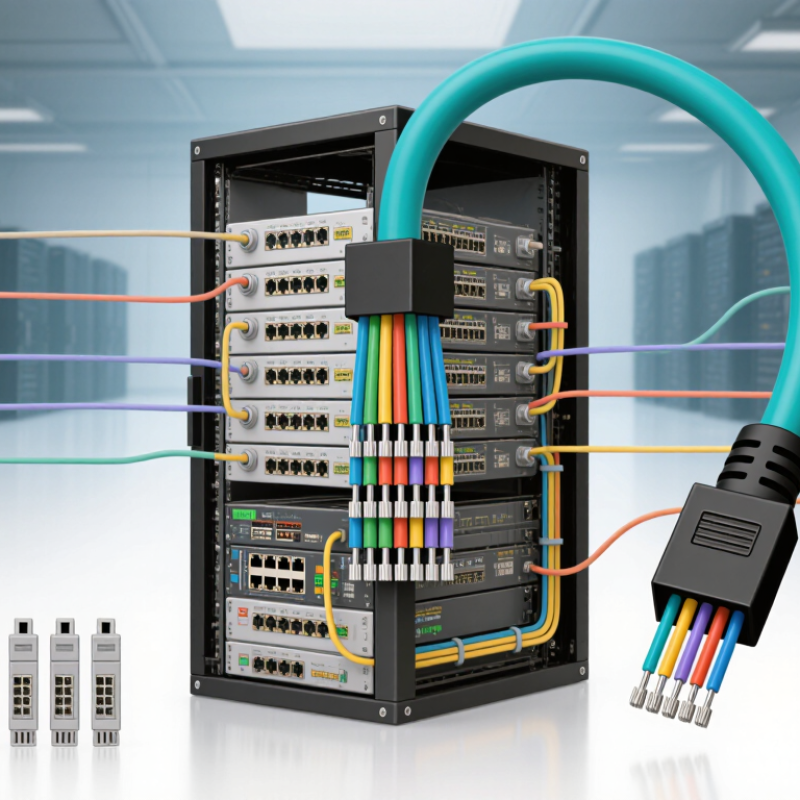
MPO Cable Definition: Multi-Fiber Connectivity in 8, 12, 16, or 24 Fibers
An MPO cable is a factory-terminated fiber assembly with one compact connector carrying multiple optical channels. Its name means multi-fiber push-on. Instead of plugging separate duplex cables into a rack, technicians connect one MPO interface and activate several fibers at once.
Fiber counts commonly include 8, 12, 16, and 24 fibers. An 8-fiber MPO often supports four transmit and four receive lanes. A 12-fiber version can serve parallel 40G or 100G links, depending on transceiver design. Sixteen-fiber assemblies suit higher-density 400G architectures. Twenty-four-fiber versions provide additional lanes, but they require careful polarity and pin mapping. The ISO/IEC 11801 cabling standard and IEC 61754-7 connector specifications guide these physical choices. LightCounting’s 2024 optical-transceiver market analysis also identifies AI clusters and high-speed interconnects as major growth drivers. The pressure is real. Yet fiber count alone does not guarantee performance.
Tips: Check the transceiver’s lane count, connector gender, key orientation, and polarity method before installation. Measure insertion loss after cleaning. A single contaminated end face can darken several lanes at once. In field work, I have seen “plug-and-play” plans fail because eight-fiber and twelve-fiber mappings were treated as interchangeable. They are not. Rechecking the design feels slow, but replacing a dense trunk later is slower. Standards help, though documentation is still imperfect.

MPO Components Explained: Ferrules, Guide Pins, Clips, and Polarity Methods
An MPO cable is a high-density fiber assembly with multiple fibers in one connector. It supports parallel transmission between switches, patch panels, and transceivers. The 2024 Ethernet Alliance roadmap highlights growing 800G and 1.6T network adoption. More lanes demand cleaner, better-controlled connections.
The ferrule holds the fiber ends in precise alignment. Its polished face must remain clean. A tiny particle can create insertion loss or reflection. Guide pins enter matching holes and keep two ferrules aligned during mating. Pinned connectors usually connect to unpinned adapters, not another pinned end. Clips secure the connector body and help prevent accidental separation. They are small, but a loose clip can interrupt service. IEC 61754-7 defines the MPO connector interface, while TIA cabling guidance addresses polarity and inspection practices.
Polarity determines each fiber’s transmit and receive path. Method A keeps fiber positions straight but reverses one end through the system. Method B reverses positions between ends. Method C uses paired reversals, which can simplify some duplex links. The chosen method must match modules, trunks, and patch cords. Uptime Institute’s 2024 Global Data Center Survey reported that 53% of respondents experienced an outage during the previous three years. That figure is not caused by MPO cables alone, yet it shows why small connection errors deserve attention. Inspecting both end faces and documenting polarity is practical. Still, technicians sometimes trust labels too quickly. Visual checks remain necessary.
How MPO Cables Transmit Data Across 40G, 100G, 400G, and Beyond
An MPO cable is a multi-fiber optical cable with one compact connector. Inside, several fibers transmit data at the same time. This parallel design helps data centers increase bandwidth without installing a separate cable for every channel. A 40G link commonly uses four lanes at 10G each. A 100G link may use four 25G lanes or other lane arrangements. The exact design depends on the transceivers and transmission standard.
At 400G, the link can use eight 50G lanes or four 100G lanes. Newer systems continue improving lane speed, modulation, and fiber counts. MPO cables therefore support more than simple point-to-point connections. They also require correct polarity, fiber mapping, and connector alignment. One reversed lane can stop the entire link. The confusing part is that similar-looking cables may support different applications. Specifications must be checked carefully.
Tips: Inspect and clean every connector before connection. Confirm the MPO type, key orientation, fiber count, and polarity method. Leave enough service slack for testing and maintenance. In real installations, small labeling mistakes often cause long troubleshooting sessions. A power meter and visual inspection tool can reveal problems early. Still, testing only one channel may be insufficient. Every active lane should be verified at its target speed.
How MPO Cables Scale Across Ethernet Speeds
MPO-based parallel optics increase total bandwidth by combining multiple optical lanes. The representative configurations shown use 4 lanes at 10G for 40G, 4 lanes at 25G for 100G, 8 lanes at 50G for 400G, and 8 lanes at 100G for 800G. Actual lane counts and MPO fiber positions vary by Ethernet standard and transceiver design.
MPO Performance Factors: Insertion Loss, Return Loss, and Fiber Density
What Is an MPO Cable and How Does It Work?
An MPO cable groups multiple optical fibers into one compact connector. Inside a data center, it can connect trunks, cassettes, and network equipment with fewer cables. Its performance depends on more than fiber count. In practice, insertion loss, return loss, and fiber density often decide whether a link remains stable after installation.
Insertion Loss and Return Loss
Insertion loss measures how much optical power disappears through connectors, splices, and fiber. Every mating point adds risk. Dust on an end face can raise loss quickly. A technician should inspect, clean, and test both ends before accepting a link. Return loss describes reflected light traveling back toward the transmitter. Poor polishing, air gaps, or mismatched components can increase reflections. High return loss is usually desirable because it means less reflected power. Test results should be recorded with calibrated equipment, not judged by appearance.
Fiber Density in MPO Cabling
Fiber density is the practical advantage of MPO cabling. A single connector may carry 8, 12, or more fibers, saving rack space and reducing cable congestion. However, dense layouts demand careful polarity control and clear labeling. One reversed fiber can disrupt several channels. I have seen neat installations fail because the mapping was assumed rather than verified. Standards-based testing helps, but field conditions are rarely perfect. Connector tolerances, bending pressure, and repeated handling still deserve attention. Higher density is useful, not automatically better.
MPO Deployment Workflow: Polarity, Cleaning, Testing, and Maintenance Standards
An MPO cable is a multi-fiber connector assembly used for high-density optical links. It carries several fibers through one compact interface. Inside a data center, this design reduces patching space and speeds installation. However, performance depends on disciplined deployment, not connector density alone.
Polarity must be verified before the cable enters a rack. Technicians should match connector keys, fiber positions, and transceiver requirements against the approved polarity method. A simple drawing prevents costly rework. It should show each end clearly. Dust is a quiet problem. Inspect both connector faces with a microscope, then clean them with approved lint-free tools. Never assume a new cable is clean. It may have collected particles during handling.
Testing should include insertion loss and polarity verification. Use calibrated equipment, reference cords, and test limits defined by the project standard. Record the cable ID, test wavelength, result, and technician. These records support dependable troubleshooting later. A failed result needs investigation, not repeated testing until it passes. Check bends, adapters, end-face damage, and incorrect mapping. We sometimes focus too much on the meter reading. The physical route may reveal the real fault. During maintenance, cap unused ports, protect trunks from sharp bends, and inspect connections after cabinet changes. Follow applicable requirements, such as ISO/IEC and ANSI/TIA structured cabling practices. Review procedures regularly. Field conditions are rarely perfect.
What Is an MPO Cable and How Does It Work? - MPO Deployment Workflow: Polarity, Cleaning, Testing, and Maintenance Standards
| Workflow Area | Technical Dimension | Recommended Practice or Standard | Why It Matters | Verification Record |
|---|---|---|---|---|
| 1. Cable Selection | Connector format | Use an MPO connector when multiple fibers must be connected in a single compact interface. Select fiber count, keying, gender, and connector type to match the equipment and adapter. | Prevents incompatible components and reduces installation rework. | Cable part description, fiber count, connector type, keying, and gender. |
| 2. Fiber Assignment | Parallel and duplex transmission | A multi-fiber MPO interface can carry parallel optical channels or connect breakout assemblies for duplex links. Confirm the intended lane-to-lane mapping before installation. | Correct mapping is essential for transmit and receive paths to align. | Fiber map showing each position, lane, and endpoint. |
| 3. Polarity Planning | End-to-end polarity method | Choose and document a polarity method that maintains the correct relationship between each transmit fiber and its corresponding receive fiber across trunks, modules, cassettes, and patch cords. | Avoids reversed channels, dark links, and time-consuming troubleshooting. | Approved polarity diagram and port-to-port mapping. |
| 4. Key Orientation | Connector key position | Inspect the key-up or key-down orientation at every mating point and verify that adapter orientation agrees with the documented polarity design. | A keying mismatch can reverse fiber positions even when the cable is otherwise suitable. | Installation checklist with connector orientation confirmed. |
| 5. Physical Installation | Routing and mechanical protection | Route the cable without exceeding its specified minimum bend radius. Protect connectors from pulling, twisting, crushing, sharp edges, and excessive tensile load. | Mechanical stress can increase attenuation or cause permanent fiber damage. | Path inspection, bend-radius check, and strain-relief confirmation. |
| 6. Connector Cleaning | End-face cleanliness | Inspect and clean every MPO end face before mating. Use lint-free materials and a cleaning method designed for multi-fiber connectors. Do not touch the end face with bare fingers. | Dust and oil can cause insertion loss, reflections, scratches, or permanent contamination. | Inspection image or pass/fail cleaning log. |
| 7. Inspection | End-face condition | Use a suitable fiber inspection microscope or probe to check all fiber positions for debris, scratches, pits, cracks, or contamination before connection. | Visual inspection helps prevent damage from transferring between mated connectors. | Inspection result for each connector and position, where applicable. |
| 8. Optical Testing | Insertion loss | Measure insertion loss with a calibrated optical light source and power meter. Test the wavelengths and fiber positions required by the link design. | Confirms that total link loss remains within the optical power budget. | Test wavelength, reference method, fiber position, measured loss, and limit. |
| 9. Fault Diagnosis | Continuity and polarity | Use a fiber identifier, continuity tester, or polarity tester to verify that each fiber reaches the intended endpoint and that the sequence is correct. | Separates polarity errors and misrouting from optical-loss problems. | Fiber-by-fiber continuity and polarity report. |
| 10. Extended Testing | Reflectance and event location | For troubleshooting or critical links, use an optical time-domain reflectometer with suitable launch and receive conditions to locate high-loss events, breaks, or reflections. | Identifies the approximate location and nature of faults that basic loss tests cannot isolate. | Trace file, test direction, wavelength, pulse settings, and event table. |
| 11. Labeling | Port and cable identification | Label both ends with unique cable identifiers, source and destination ports, fiber count, and polarity reference. Keep labels readable and securely attached. | Improves moves, adds, changes, and fault response accuracy. | Cable schedule and updated rack or cabinet documentation. |
| 12. Protective Caps | Unused connector protection | Keep dust caps installed on every unmated MPO connector. Store removed caps in a clean location and do not place contaminated caps back on inspected end faces. | Reduces contamination during storage, transport, and future maintenance. | Visual check during installation and maintenance rounds. |
| 13. Maintenance | Inspection and cleaning frequency | Inspect and clean connectors whenever a link is disconnected, after exposure to dust or construction activity, or when test results show abnormal loss. Schedule periodic checks for high-density environments. | Preventive care reduces intermittent faults and unplanned downtime. | Maintenance date, technician, connector inspected, action taken, and result. |
| 14. Change Control | Documentation accuracy | Update polarity diagrams, port assignments, test records, and cable routes after every approved change. Retain baseline and post-change test results. | Accurate records make future expansion and troubleshooting faster and safer. | Revision-controlled layout, work order, and acceptance test report. |
General acceptance principle: An MPO link should be considered ready for service only after connector cleanliness, polarity, physical routing, fiber continuity, optical loss, labeling, and documentation have all been verified.

