
How to Choose the Right Arm Cylinder for Your Equipment?
Choosing the right Arm Cylinder begins with more than matching bore size to lifting force. It requires a careful look at the machine, workload, environment, and maintenance habits. A cylinder that performs well on a clean factory floor may struggle under mud, saltwater, dust, or repeated side loading. Small details matter. Pin diameter, stroke length, mounting style, rod coating, seal material, and operating pressure can decide whether the equipment works smoothly or fails early.
Hydraulic engineer Peter Nachtwey often emphasizes, “A cylinder is only as reliable as the system supporting it.” This practical view should guide every selection. The pump must provide stable flow. The valve must control movement accurately. The structure must keep the rod aligned. Even a premium Arm Cylinder cannot correct contaminated oil or a bent mounting bracket.
Begin with real measurements, not assumptions. Record the required stroke, retracted length, maximum load, cycle speed, and available installation space. Then consider shock loads, temperature changes, corrosion, and daily cycle frequency. A 100-millimeter bore may appear sufficient, yet pressure spikes can expose a weak design. It is also easy to oversize the cylinder. That choice may increase cost, weight, and energy use without improving performance.
There is no perfect specification for every machine. Field experience often reveals gaps in the original calculation. A careful selection process leaves room for those lessons, inspection feedback, and future operating changes. That is how the right Arm Cylinder becomes a dependable part of the entire hydraulic system.
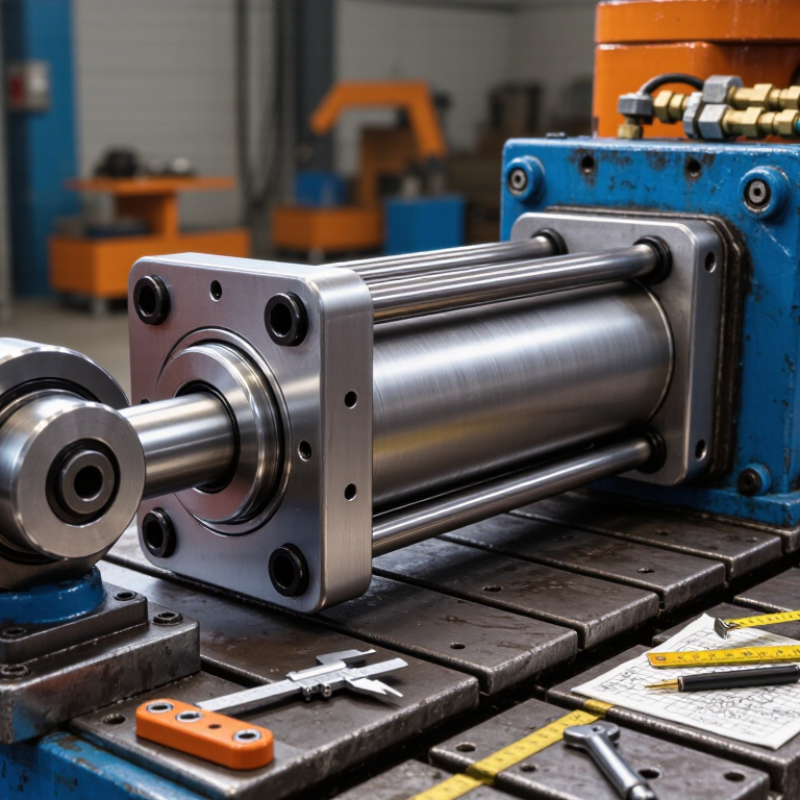
Understanding Arm Cylinder Types and Their Working Principles
An arm cylinder is a hydraulic actuator that controls an equipment arm’s reach, angle, and digging force. Choosing it requires more than matching bore diameter or overall length. The cylinder must suit the machine’s working load, hydraulic pressure, stroke, and mounting geometry.
Single-acting cylinders extend through hydraulic pressure and return by gravity or an external load. They are simple, but their movement can be less controlled.
Double-acting cylinders use pressure on both sides of the piston. This design provides powered extension and retraction, which is common for excavator arms and lifting equipment.
Telescopic cylinders offer long movement from a shorter closed length. However, their multiple stages need careful maintenance and accurate load calculation.
Inside the cylinder, pressurized oil pushes against the piston. The piston rod then transfers force through a pin connection. A larger bore creates greater pushing force, while a larger rod improves resistance to bending. Stroke length controls the arm’s range of movement. In field inspections, I check rod scoring, oil leakage, pin wear, and uneven motion before recommending replacement. A useful calculation is force equals pressure multiplied by piston area. Still, this estimate ignores friction, side loading, and pressure losses. That is where selection often goes wrong. Measure the original cylinder carefully, including retracted length, stroke, port position, and mounting width. I have found that small alignment errors can cause seal damage surprisingly quickly. 马会

Assessing Equipment Requirements and Operating Conditions
Choosing the right arm cylinder starts with the equipment, not the cylinder catalogue. Measure the arm’s required stroke, retracted length, pivot geometry, and maximum working load. Include the weight of attachments and material. A bucket filled with wet soil can exceed dry-load estimates by a surprising margin. I once saw a design pass a basic load check but struggle near full extension. The leverage changed everything.
Operating conditions matter just as much. Record system pressure, available flow, cycle frequency, and expected movement speed. A cylinder sized only for peak force may move too slowly during repetitive work. Check the mounting pins, bushings, and alignment carefully. Side loading can damage the rod and seals, even when pressure remains within limits. Uneven ground creates additional shock loads. So does sudden stopping.
Temperature, dust, moisture, and corrosion also influence cylinder selection. Use sealing and surface protection suited to the actual environment. Cold weather can thicken hydraulic fluid and reduce response. High heat may shorten seal life. Inspect the rod for scoring after trial operation. Small marks often become leaks later. Protection is not optional.
Allow a practical safety margin, but avoid excessive oversizing. A larger cylinder may require stronger mounts, more hydraulic flow, and heavier supporting structures. Verify the design with real duty-cycle data, not one ideal test. If operating information is incomplete, pause and measure it. Guessing is cheaper only at the beginning.
Matching Cylinder Size, Force, Stroke, and Mounting
How to Choose the Right Arm Cylinder for Your Equipment?
Choosing an arm cylinder starts with the real load, not the old cylinder’s label. Measure the lifted weight, linkage angle, working pressure, and available space.
A 50 mm bore at 160 bar produces about 31.4 kN theoretically. Friction and side loading reduce the usable output.
Stroke must match the arm’s actual movement. Too little stroke limits reach. Too much stroke adds weight, cost, and impact risk. Select the smallest practical bore that meets the peak load with a safety margin.
ISO 4413 recommends controlling hydraulic risks through suitable design, maintenance, and protection against unexpected movement. That matters near the final few millimeters of travel.
Mounting often decides whether the cylinder survives. Use spherical bearings or clevis joints when the arm changes angle. Keep the rod aligned with the load.
Side loading can damage seals and bend rods, even when force calculations look correct.
A 2024 Grand View Research market analysis estimates the hydraulic cylinders market will grow at roughly 4.8% annually through 2030, reflecting continued use in mobile and industrial machinery. Still, market growth does not validate every specification. Check pin diameter, retracted length, cushion settings, and oil compatibility on the machine itself.
I would recheck the calculation after observing one full work cycle.
Real motion exposes mistakes.
Comparing Materials, Seals, and Hydraulic Performance
Choosing the right arm cylinder starts with its working environment, not just its rated force. Steel barrels suit demanding loads, while stainless steel helps resist moisture and corrosive exposure. However, heavier materials can reduce efficiency and increase mounting stress. A practical choice balances strength, weight, temperature, and maintenance access.
Seals deserve equal attention. Polyurethane seals often handle abrasion well, while PTFE-based seals can perform smoothly under changing temperatures. Rubber compounds may suit moderate conditions, but compatibility with hydraulic fluid is essential. I have seen premature leakage caused by a seal chosen from pressure data alone. That was an avoidable mistake. Check temperature, fluid type, side loading, and contamination before approval. The rod surface also matters; a poor finish can damage even a high-quality seal.
Tips: Measure the real load, including shock forces. Confirm pressure at the cylinder, not only at the pump. Compare extension speed under working flow. A larger bore increases force, but it may slow movement. Inspect the mounting alignment carefully. Misalignment creates uneven wear and shortens seal life. If the machine works outdoors, specify corrosion protection and wiper seals. Keep a small safety margin, but avoid oversized components that waste energy. Test the cylinder during cold starts and peak loads, because laboratory performance may not reflect field conditions. Recheck the selection after installation; actual vibration can reveal assumptions that looked reasonable on paper.
Checking Compatibility, Safety, Maintenance, and Service Life
How to Choose the Right Arm Cylinder for Your Equipment?
Choosing an arm cylinder starts with accurate measurements, not appearance. Check the retracted and extended lengths, stroke, bore size, pin diameter, and mounting width. The cylinder must match the equipment’s hydraulic pressure and flow requirements. A small mismatch can cause slow movement, excessive heat, or premature seal failure. Confirm the cylinder’s load rating under real working conditions. Soil, uneven ground, and repeated shock loads can change performance. Experience shows that alignment matters as much as strength. Even a powerful cylinder may bend when the mounting points are not parallel.
Safety should remain visible during every inspection. Depressurize the hydraulic system before removing fittings or pins. Support the arm with approved mechanical blocks, never hydraulic pressure alone. Check for wet rod surfaces, damaged hoses, loose retainers, and unusual movement. Never place hands near a moving joint. Maintenance extends service life when the rod stays clean and the mounting pins receive suitable lubrication. Replace worn seals before contamination enters the cylinder. Keep simple service records, including operating hours and leak observations. I have seen operators ignore a minor leak until the machine lost control. That delay was avoidable.
Tips: Measure twice. Compare pressure ratings. Inspect after hard cycles. Keep spare seals available. Avoid forced installation. Review the manual when uncertain. A cylinder can look correct and still be unsuitable. Recheck your assumptions before purchase.
How to Choose the Right Arm Cylinder for Your Equipment? - Checking Compatibility, Safety, Maintenance, and Service Life
| Equipment Category | Typical Operating Weight | Typical Bore × Rod Diameter | Common Stroke Range | Recommended Working Pressure | Approx. Push Force at 200 bar | Mounting and Compatibility Checks | Safety Requirements | Routine Maintenance | Indicative Service-Life Target |
|---|---|---|---|---|---|---|---|---|---|
| Mini excavator arm | 1–6 tonnes | 50–80 mm × 30–50 mm | 400–900 mm | 160–210 bar | 39–101 kN | Check pin diameter, center-to-center length, mounting width, rod-end thread, hydraulic-port size, and hose routing. | Use a rated relief valve; block and mechanically support the arm before service. | Inspect rod and seals daily; lubricate pins according to the equipment manual; keep hydraulic oil clean. | Approximately 5,000–10,000 operating hours, depending on loading and contamination control. |
| Compact excavator arm | 6–12 tonnes | 80–110 mm × 50–70 mm | 700–1,300 mm | 200–250 bar | 101–190 kN | Confirm retracted and extended lengths, pin-boss alignment, cylinder angle, bearing clearance, and available installation space. | Verify pressure rating exceeds the machine relief setting; use hose protection near articulation points. | Check leakage, bent-rod marks, loose retainers, and abnormal drift; replace damaged wipers promptly. | Approximately 6,000–12,000 operating hours under controlled loads and regular filtration. |
| Standard excavator arm | 12–25 tonnes | 100–150 mm × 70–100 mm | 900–1,700 mm | 250–350 bar | 157–353 kN | Match the original cylinder’s geometry, cushioning arrangement, port orientation, pin retention, and hydraulic flow requirements. | Install a pressure-rated cylinder with compatible hoses and fittings; never test leaks by hand. | Sample oil periodically; inspect chrome plating and welds; check pin bushings for side loading. | Approximately 8,000–15,000 operating hours when shock loads and side loads are minimized. |
| Large excavator arm | 25–50 tonnes | 140–200 mm × 90–140 mm | 1,200–2,200 mm | 300–350 bar | 308–628 kN | Verify structural loads, cylinder mass, pin shear capacity, mounting weld condition, and sufficient clearance through the complete arm cycle. | Use correctly rated lifting equipment during installation; depressurize and lock out the hydraulic system. | Use scheduled oil analysis; inspect gland, piston, and cushion components during planned shutdowns. | Approximately 10,000–20,000 operating hours, subject to duty cycle and impact exposure. |
| Loader or articulated-boom arm | 5–30 tonnes | 80–180 mm × 50–120 mm | 600–1,800 mm | 200–350 bar | 101–509 kN | Check load direction, articulation angle, rod-side and cap-side port placement, mechanical stops, and synchronization with paired cylinders. | Confirm load-holding or hose-burst protection where required by the application and local regulations. | Inspect for side loading, uneven extension, seal leakage, and contamination around the rod wiper. | Approximately 6,000–15,000 operating hours, depending on shock loading and duty severity. |

