
How to Choose ABB Power Factor Correction Capacitors?
Choosing Abb Power Factor Correction Capacitors is not simply a matter of matching a kvar value to a motor. A reliable selection begins with the site’s measured load profile, voltage level, harmonic content, and operating schedule. A capacitor bank that performs well beside a lightly loaded pump may behave poorly near variable-frequency drives. Real conditions matter.
Roger C. Dugan, a widely recognized power-quality engineer, offers a useful principle: “Power factor correction is a system-design decision, not merely a capacitor purchase.” This idea should guide every ABB Power Factor Correction Capacitors assessment. Engineers should review transformer capacity, switching frequency, inrush current, ambient temperature, and expected load growth. They should also confirm whether automatic steps are needed for fluctuating demand.
Look inside the panel.
A practical inspection may reveal warm terminals, swollen capacitor cans, repeated fuse failures, or audible switching stress. These details can signal overvoltage, excessive harmonics, poor ventilation, or incorrect step control. Where harmonic-producing equipment is present, detuned reactors may be necessary to reduce resonance risk. However, reactor selection must follow measured data, not assumption.
Experience also teaches humility. Nameplate calculations can miss actual operating behavior. A bank may improve the power factor yet create new maintenance problems. Therefore, this guide compares kvar sizing, voltage ratings, harmonic protection, controller settings, enclosure conditions, and lifecycle reliability. The best choice is not always the largest bank. It is the bank that remains stable, cool, and predictable under real operating conditions.
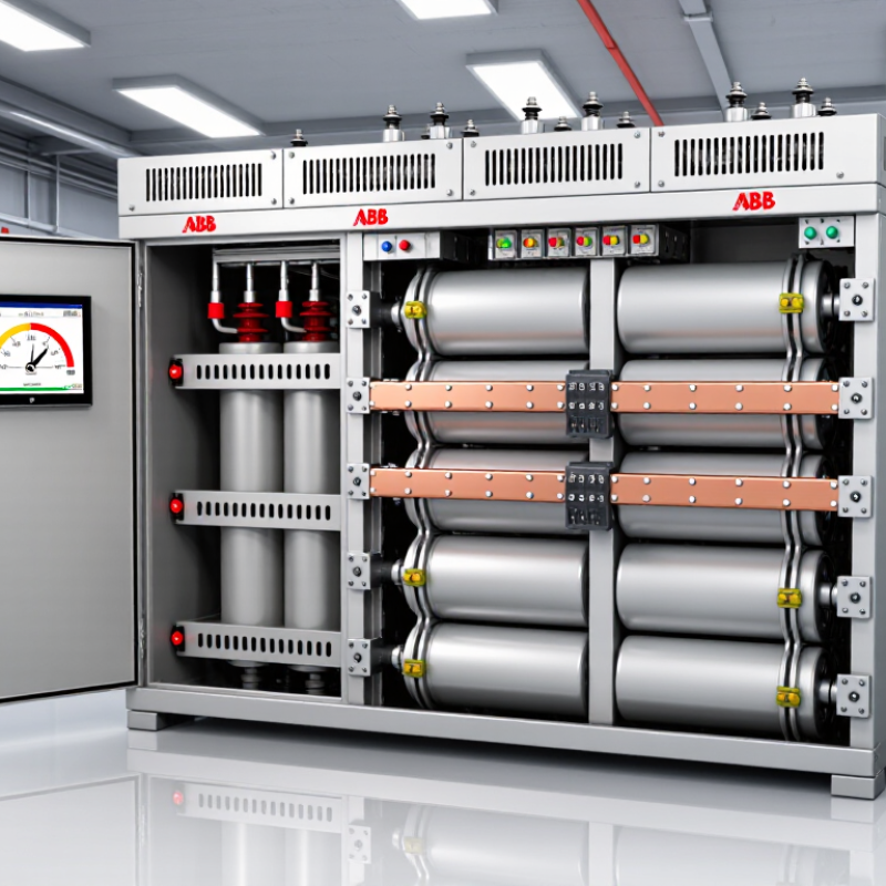
Table of Contents [Hide]
Assess Load Profile, Power Factor, and Harmonics Before Selection
Choosing power factor correction capacitors starts with measuring the real load profile, not guessing from one meter reading. In a factory, demand can shift sharply when compressors, welders, and motors start. Record kW, kvar, current, voltage, and power factor at short intervals during representative shifts. Include weekends if production changes. A snapshot is not enough.
Compare average and peak reactive demand before sizing capacitor steps. Oversized banks may create a leading power factor during light-load periods. That condition can increase voltage stress and switching problems. Set step sizes around actual operating changes, rather than using one large stage. Check motor starting currents and automatic controller response. I have found that banks sized from monthly billing data often miss short, severe peaks. Billing data is useful, but incomplete.
Harmonic assessment is equally important. Variable-speed drives, rectifiers, uninterruptible power supplies, and LED drivers can distort the waveform. Measure total harmonic distortion at the main bus and near nonlinear loads. Capacitors can interact with system inductance and amplify harmonics. If measurements show risk, consider detuned reactors or a properly engineered harmonic filter. Verify voltage rating, discharge resistors, enclosure temperature, and switching duty. The first design may need adjustment after field readings.
How to Choose ABB Power Factor Correction Capacitors? - Assess Load Profile, Power Factor, and Harmonics Before Selection
| Load Profile | Typical Operating Power Factor | Typical Current THDi | Common Harmonic Sources | Recommended Capacitor Arrangement | Detuning Guidance | Control and Switching Strategy | Key Selection Checks |
|---|---|---|---|---|---|---|---|
| Predominantly linear motor and transformer loads | 0.80–0.90 lagging | Usually below 5% | Induction motors, transformers, heaters, and conventional lighting | Standard shunt capacitor bank may be suitable when the resonance study is clear. | Reactor may not be required, but system impedance and background harmonics should be verified. | Automatic stepped switching is normally suitable for variable production schedules. | Check minimum load, transformer capacity, existing capacitors, and the risk of leading power factor during lightly loaded periods. |
| Variable-frequency-drive dominated process | 0.75–0.90 lagging, depending on drive type and loading | Approximately 25–45% for many six-pulse drives without harmonic mitigation | Rectifier front ends in motor drives and DC-link converters | Use a harmonic-resistant, detuned capacitor bank rather than an ordinary non-detuned bank. | Common detuning choices include approximately 5.67% or 7%; the final value requires a resonance and harmonic assessment. | Use staged switching with discharge resistors and switching delays suitable for frequent load changes. | Review drive quantity, drive ratings, short-circuit strength, transformer impedance, and total harmonic voltage distortion. |
| Uninterruptible power supply and data-processing loads | 0.80–0.95 lagging or near unity, depending on rectifier design | Approximately 5–40% | UPS rectifiers, switched-mode power supplies, servers, and battery chargers | Use detuned correction only after confirming the UPS input characteristics and generator operating mode. | Detuning is often appropriate where nonlinear loads are significant; confirm compatibility with bypass and generator operation. | Use fast but controlled automatic steps; avoid excessive switching during rapid load fluctuations. | Check generator capacity, UPS input power factor, bypass operation, neutral loading, and harmonic limits at the point of common coupling. |
| Welding machines, arc furnaces, and rapidly fluctuating loads | 0.60–0.85 lagging | Approximately 20–60%, with possible rapid variation | Arc equipment, welding rectifiers, and power-electronic converters | Consider dynamic compensation, such as switched electronic compensation or a power-quality system, instead of a fixed capacitor bank. | Do not select detuning from THDi alone; perform a detailed frequency scan and evaluate voltage distortion. | Use fast-response control with adequate switching endurance and current-limiting protection. | Assess flicker, voltage fluctuations, interharmonics, unbalance, short-circuit level, and the speed of reactive-power changes. |
| Commercial buildings with LED lighting and electronic equipment | 0.85–0.98 lagging, depending on equipment quality and operating level | Approximately 10–30% | LED drivers, computers, displays, office power supplies, and small HVAC drives | Use a small stepped bank only after measuring the aggregate load profile and harmonic spectrum. | Detuned capacitors are advisable when the building has substantial nonlinear load or a high density of electronic equipment. | Use automatic steps sized for low daytime and nighttime demand to prevent overcorrection. | Check minimum demand, third-harmonic current, neutral conductor loading, and the effect of standby generators. |
| Mixed industrial facility with changing production schedules | 0.75–0.95 lagging | Approximately 10–40% | Motors, transformers, drives, welders, lighting, and power supplies | Use a measured, automatic, detuned bank when nonlinear loads are material; combine with harmonic filtering if necessary. | Select the detuning percentage from a network study, not from a standard value alone. | Use multiple steps with load-dependent control, switching interlocks, and alarms for abnormal voltage or current. | Measure at least one representative operating cycle, including maximum production, minimum load, and major equipment start-up. |
| Facility supplied by a standby generator | 0.80–0.95 lagging before correction | Depends on connected nonlinear loads and generator impedance | Drive rectifiers, UPS systems, electronic lighting, and generator voltage-regulator interactions | Use generator-compatible, automatically controlled correction with conservative switching limits. | Verify resonance separately for utility and generator operation because generator impedance is typically higher. | Interlock or reduce capacitor stages during generator operation when required by the system study. | Check generator kVA, transient stability, minimum loading, excitation-system limits, and leading power-factor tolerance. |
Practical sizing and verification notes: A preliminary capacitor requirement can be estimated with Qc = P × (tan φ₁ − tan φ₂), where P is active power, φ₁ is the initial power-factor angle, and φ₂ is the target power-factor angle. A typical target is approximately 0.95–0.99 lagging; avoid creating a leading power factor. Confirm capacitor RMS current, continuous overvoltage capability, inrush current, discharge time, enclosure conditions, and compatibility with the intended detuned reactor before final selection.